1 Sadly, this is the only "before" picture, perhaps just as well. The surveyor noted an electrical problem to be attended to, namely, that the batteries were just sitting in the bilge, held in place by the cables and their own weight; attrocious. This prompted a closer examination of the wiring and what I found ranged from terrible to just plain dangerous. Wires were dangling loose, speaker wire was used extensively for power cables (including the bilge pump!), the wrong size wire was used and so on. There was actually a pair of speaker wires with bared ends connected directly to the battery! No switch, no fuse, nothing. A major rework was in order. |
 2 It was decided to relocate the batteries to the cabin, under a settee. They would be better protected, easier to replace, easier to monitor it would actually be a shorter path to the starter motor. All the other wires would then be protected in conduit. If you could see it, or grab it or even touch it, it was going into conduit. Here we see all the wire from the previous pic now protected. |
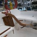
 3 Even the conduit is protected where possible, here being tucked up under the coaming. |
 4 Here's SOME of the wiring for the autopilot computer. Next step will be to install a waterproof box and then bolt in the computer. Pulling these wires was tough, given the long runs and awkward location. Annoyingly, I kept thinking of things that needed direct connection to the autopilot computer and actually had to pull a bunch more cable. |
 5 The grey cables are data cables, a pair of three wire with shield, a four wire with shield and a 10 conductor. There's some 12 gauge power cable and another run of 16 gauge power cable, just in case. |
 6 As the look on my face tells you, this was NO FUN. It was cramped, dark and smelly. And I only had to get out and crawl back in about a hundred times. Once I got a cramp, but couldn't move because of the contortions required to just get in. Another time, my pants got caught on a protruding bolt and I could NOT get out! I couldn't get my hands around back to free myself. I had visions of dying there with the newspaper headline reading "man's new boat kills him in freak accident". |
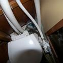
 7 If you look hard here, you can see a pair of black panels above the orange fire extinguisher. These are the DC switch/breaker panels. They're going to be removed. Then there's the white VHF unit and beside it the black stereo. These too will be moved. Beneath the stereo is a large cubby hole. This will be the new DC wiring hub. If you look hard, you can see a white plastic tube. The propane hose for the water heater runs inside this tube, with LOTS of room to spare. This is important because while that cubby hole has lots of room, there's just no way to get the wire to it from overhead. So this conduit will do double-duty, protecting the propane hose as well as the low power electrical cables. High power cables that might concieveably get hot are not run inside this tube. |
 8 The area that was previously the DC hub is now the AC hub, with a custom made breaker panel. The main switch feeds the other breakers as well as the duplex outlet above it. This outlet is tied directly to the shore, and so the "ground" is an electrolysis consideration/problem. Basically, it will ONLY be used short term, and only when people are present, typically for tools. Anything left on and unattended will be connected to the only other duplex outlet on board, which is connected to an isolation transformer. Middle breakers power the battery charger, also isolated. And that's it for AC; this is a sailing vessel, not a docking vessel. |
 9 And so it begins, with ceiling panels removed, old cables ripped out and new ones being installed. |
 10 |
 11 |
 12 |
 13 |
 14 This goofy box used to house the radar unit, with a plexiglass cover allowing it to be seen from the cockpit. Now, radar visible from the cockpit is a very good idea, but the implementation left something to be desired. The radar will instead be surface mounted on a big slab of teak, still visible from the cockpit, along with the chartplotter and autohelm control. In back will be the "navigation electronics" centre, as there is going to be a whole whack of electronics going in. (I just can't resist) You can see white tape at the end of the wires. I was religious about properly labelling both ends of EVERY cable I put in with the right 3M numbering product, and then went a step further by protecting the numbers with a length of clear heat-shrink tubing. |
 15 The white through-hull fitting in the middle of the picture is for the deck mounted nav electronics. |
 16 And here it is out the top. There will be a basic GPS and sounder, as well as a handheld GPS/Chartplotter. Since I already own these, I figure I may as well wire them up. The little chartplotter will be eventually replaced; it's hard to read with my old eyes, but DOES work and DOES come with the expensive detailed map, so I'll use it until I break down and buy a bigger one. The fat red and black wires are for the solar panel, mounted atop the dodger. The grey cable is for an external GPS antenna. |
 17 Here we see the overhead wiring now pulled and secured. The aluminum plate is a backing plate for the traveller mount above. The original traveller arrangement leaked, into the cabin and into the deck! and so a serious project was required to fix this, interrupting the wiring project. |
 18 Port side wiring. |
 19 Eventually, everything ends up where we want. In the back is a home made buss bar for the ground wires. I had a nice thick slab of copper (saved for probably 20 years) that I drilled some holes in; done. The batteries are located beneath the settee immediately beneath this spot, so it's a short run from the batteries. You can see a fat red wire here; that's a six gauge wire, entirely adequate for what's being switched above. Everything high power (windlass, toilet and macerator pump) will get power from right down near the batteries and will be remotely switched. A close look shows some orange wires; these are the control lines for the solid state switches. |
 20 And here's the electrical area, now complete. Since nothing in this opening is square, parallel or perpendicular, everything on the plate looks crooked. Life with a boat. |
 21 Here's the front side of meter module. |
 22 Here's the relocated starter battery, with the main switch and various high current fuses. |
 23 And the house battery. Another home made buss bar, again made from 1/4" thick copper plate. |
 24 And the completed battery area. In the middle are two cutout switches. The battery positives go directly to these switches, so it's possible to COMPLETELY disconnect one or both batteries. On the left is windlass breaker, sandwiched between a pair of fuse blocks. These blocks, one for the House battery, one for the Starter battery, handle anything that does not go through the main House Power switch. Currently, this includes the AC battery charger, the solar cell and the bilge pumps. These of course have fuses at the far end as well, so things are fused coming and going. |
 25 Here's the back side of the panel. |
 26 A 6 gauge cable comes up from the main power switch and into this box where it goes to an ammeter shunt, mounted on the yellow nylon spacer on the left. The other side of the shunt goes to a 10 pin high current connector, shown on the left. The shunt is connected to a circular MIL connector, on the top, which everntually gets to the ammeter. |
 27 And the back side of the meter panel. Here's another circular MIL connector that goes to both batteries and the ammeter. Inside the box you can just see a relay. This allows me to turn the meters on or off, saving a tiny bit of power if required. |